Exploring My Homelab: Mikrotik Networking and Proxmox Servers
A deep dive into my homelab setup: dual Mikrotik routers, high-speed LAN, multiple VLANs, and a dedicated server network.
Introduction
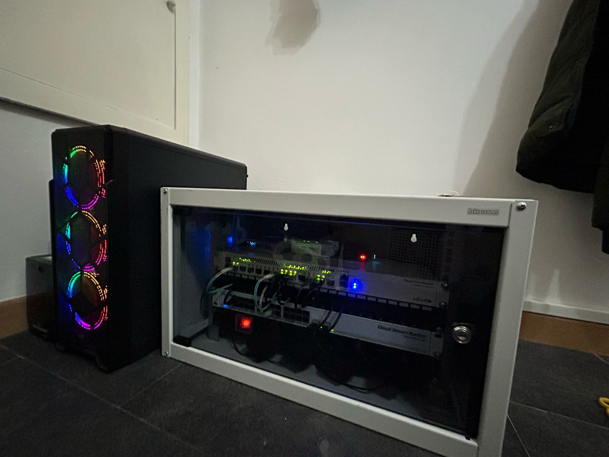
My homelab is quite complex—many of the complications are not strictly necessary, but they have allowed me to experiment, learn, and grow my understanding of advanced networking and virtualization. In this article, I’ll walk through the structure of my network and server infrastructure, hosted inside a 6U BTicino rack.
Core Network Setup
At the heart of the rack sits the ONT provided by my ISP, Telecom Italia. My residential-grade plan offers 10 Gbit/s download and 2 Gbit/s upload, along with 4 dynamic public IPs.
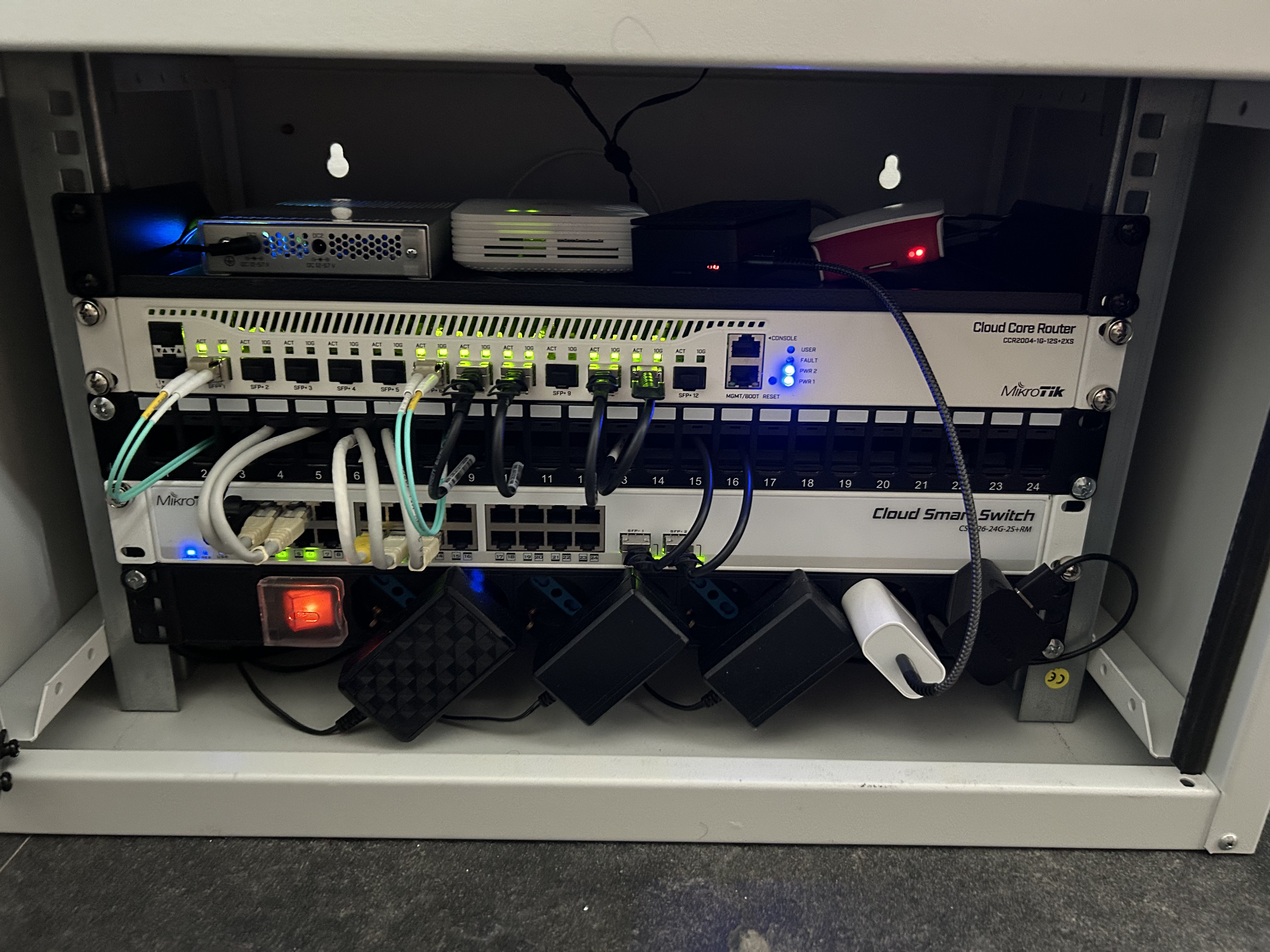
From the ONT, an Ethernet cable runs into a Mikrotik CRS305-1G-4S+IN switch via a Mikrotik S+RJ10 module. While it might look unusual to connect the ONT to a switch rather than a router, this approach lets me split the internet connection across two routers:
- LAN Router — Mikrotik CCR2004-1G-12S+2XS
- Server Router — Mikrotik CCR2004-1G-2XS-PCIe (installed directly in my main server via PCIe)
This design adds complexity but enables a clean separation between my home LAN and server network.
LAN Router (CCR2004-1G-12S+2XS)
Most of my daily-use devices, such as my desktop PC, are directly connected to the router’s SFP+ ports, allowing full 10 Gbit/s speeds both inside the LAN and to the outside world.
To feed all copper Ethernet devices, the LAN router uplinks (bonded over two SFP+ ports) to my access/core switch—the Mikrotik CRS326-24G-2S+RM—described in the next section.
VLANs and Subnets
The LAN is divided into multiple networks defined on the router:
- Main LAN:
192.168.10.0/24 - Guest (VLAN 20):
192.168.20.0/24 - IoT (VLAN 30):
192.168.30.0/24
Firewall policies enforce segmentation between these networks.
Access/Core Switch: Mikrotik CRS326-24G-2S+RM
The CRS326-24G-2S+RM is the copper workhorse that distributes connectivity to wired clients and access points.
Uplink & Throughput
- The switch is connected to the CCR2004 with a bonded 10G uplink using the two SFP+ ports for aggregate bandwidth and redundancy (LACP/802.3ad).
- The bonded uplink carries all VLANs as a trunk.
Port Roles
- Trunk Ports: The SFP+ uplink(s) to the router carry VLAN 10/20/30 tagged.
- Access Ports: Regular client ports are assigned a PVID for the appropriate network (e.g., untagged on VLAN 10 for the main LAN).
- AP Uplinks: The two Ubiquiti UAP-AC-Pro access points are connected to dedicated switch ports configured as trunk or access according to SSID/VLAN mapping. (AP management stays reachable; guest and IoT SSIDs map to VLAN 20 and VLAN 30 respectively.)
- Note: The CRS326-24G-2S+RM does not provide PoE on its RJ45 ports, so the APs are powered via PoE injectors (or an external PoE switch).
Switching Features
- Bridge VLAN filtering is enabled to enforce VLAN segmentation in hardware.
- RSTP is active to protect against accidental loops.
- LLDP helps with neighbor discovery and documentation.
- Optional performance tweaks like jumbo frames are supported end-to-end when all participating devices match MTU.
This layout lets me keep the high-speed 10G backbone between router and switch while cleanly segmenting traffic to clients.
Server Router & Network (CCR2004-1G-2XS-PCIe)
For the server side, I deliberately introduced another layer of complexity by dedicating a separate router: the Mikrotik CCR2004-1G-2XS-PCIe.
This choice wasn’t strictly necessary—I could have created a separate network on the CCR2004-1G-12S+2XS—but I preferred to physically and logically separate environments.
The two routers communicate over a dedicated point-to-point subnet (192.168.100.0/30), and I allow communication only from the LAN side toward the servers. That keeps exposure minimal while making management straightforward from my main network.
Why This Complexity?
I’ll admit: much of this setup is not required for a typical home environment. However, the extra steps—splitting routers, running VLANs, experimenting with firewalls and LACP—have been incredibly valuable for hands-on learning.
Through this homelab, I’ve gained experience with:
- Multi-router edge designs with public IP allocation
- High-speed 10 Gbit/s switching and routing
- VLAN design and inter-VLAN policies
- LACP bonding and redundancy
- Wireless segmentation for Guest and IoT
Conclusion
My homelab may be overengineered, but that’s exactly the point—it’s a testing ground where I can experiment with advanced configurations and gain real-world knowledge. In a follow-up, I’ll what services im running in my Homelab.